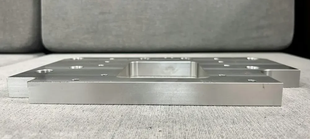
Many drawings carry one short note in the title block, such as “ISO 2768-m”, and leave every other dimension untoleranced. That note is doing a lot of work: it sets the tolerance for every length, radius and angle that has no tolerance of its own. This guide explains what each ISO 2768 class allows, which features on CNC machined plates and brackets should never rely on it, and how ISO 2768 relates to IT grades.
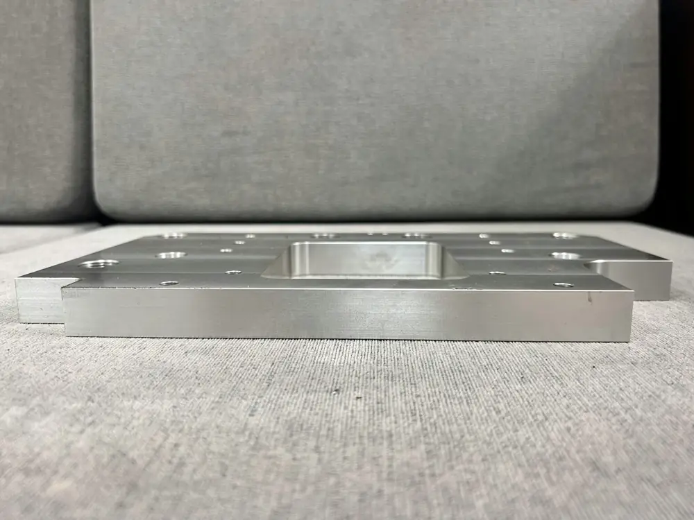
What ISO 2768 covers
- ISO 2768-1 sets general tolerances for linear dimensions, external radii and chamfers, and angles. It has four classes: f (fine), m (medium), c (coarse) and v (very coarse).
- It applies only to dimensions without an individual tolerance. A dimension with its own tolerance, such as Ø6 H7, follows that tolerance instead.
- It does not cover threads. Threads follow their own tolerance class, such as 6H for internal metric threads.
When to use ISO 2768, and when not to
| Use the general tolerance for | Give an individual tolerance for |
|---|---|
| Outer profile and non-functional lengths | Dowel pin holes and other press or slip fits |
| Pockets, clearance cuts and weight-reduction features | Bearing bores and shaft seats |
| Clearance holes for bolts with generous clearance | Hole patterns that must line up with a mating part |
| Cosmetic edges, radii and chamfers | Seal and O-ring grooves |
| Early prototypes where the design is still changing | Thicknesses that add up in a stacked assembly |
Choosing a class: f, m, c or v
- m (medium) is the most common choice for CNC machined parts and the right default for most plates and brackets.
- f (fine) suits small, compact parts where everything needs to be closer. It tightens every untoleranced dimension, so it increases machining and inspection effort across the whole part.
- c (coarse) and v (very coarse) suit large fabricated, welded or rough parts, not typical machined components.
A common mistake is switching the whole drawing from m to f because one hole spacing needs to be tighter. Every outline dimension gets tighter too, and the critical hole spacing may still not be tight enough. Keep m and tolerance the critical feature individually.
ISO 2768-1 linear tolerances (mm)
| Nominal size (mm) | f | m | c | v |
|---|---|---|---|---|
| 0.5 – 3 | ±0.05 | ±0.1 | ±0.2 | — |
| over 3 – 6 | ±0.05 | ±0.1 | ±0.3 | ±0.5 |
| over 6 – 30 | ±0.1 | ±0.2 | ±0.5 | ±1 |
| over 30 – 120 | ±0.15 | ±0.3 | ±0.8 | ±1.5 |
| over 120 – 400 | ±0.2 | ±0.5 | ±1.2 | ±2.5 |
| over 400 – 1000 | ±0.3 | ±0.8 | ±2 | ±4 |
| over 1000 – 2000 | ±0.5 | ±1.2 | ±3 | ±6 |
| over 2000 – 4000 | — | ±2 | ±4 | ±8 |
Example: a 200 mm long mounting plate toleranced to ISO 2768-m may be ±0.5 mm in length. At class f, the same length is ±0.2 mm.
External radii and chamfers (mm)
| Nominal size (mm) | f and m | c and v |
|---|---|---|
| 0.5 – 3 | ±0.2 | ±0.4 |
| over 3 – 6 | ±0.5 | ±1 |
| over 6 | ±1 | ±2 |
Angular tolerances
The row is chosen by the length of the shorter side of the angle.
| Shorter side (mm) | f and m | c | v |
|---|---|---|---|
| up to 10 | ±1° | ±1°30′ | ±3° |
| over 10 – 50 | ±0°30′ | ±1° | ±2° |
| over 50 – 120 | ±0°20′ | ±0°30′ | ±1° |
| over 120 – 400 | ±0°10′ | ±0°15′ | ±0°30′ |
| over 400 | ±0°5′ | ±0°10′ | ±0°20′ |
What the “K” in ISO 2768-mK means, and why it is outdated
Many drawings say “ISO 2768-mK”. The first letter is the linear class from ISO 2768-1. The second letter, H, K or L, comes from ISO 2768-2, which set general geometrical tolerances such as flatness, perpendicularity, symmetry and runout. A few values from the old tables:
| Characteristic | H | K | L |
|---|---|---|---|
| Straightness / flatness, over 30 – 100 mm | 0.1 | 0.2 | 0.4 |
| Straightness / flatness, over 100 – 300 mm | 0.2 | 0.4 | 0.8 |
| Perpendicularity, shorter side up to 100 mm | 0.2 | 0.4 | 0.6 |
| Circular runout | 0.1 | 0.2 | 0.5 |
ISO 2768-2 was withdrawn in 2021 and replaced by ISO 22081:2021, which does not use the H, K and L classes. ISO 2768-1 is still published, and a revised edition is being released. In practice:
- Existing drawings with “mK” are still common. Agree with your supplier how they will be read rather than changing the interpretation silently.
- On new drawings, put flatness, perpendicularity and position on the faces and holes that matter as individual geometric tolerances, and reference the edition, for example “General tolerances: ISO 2768-1:1989 m”.
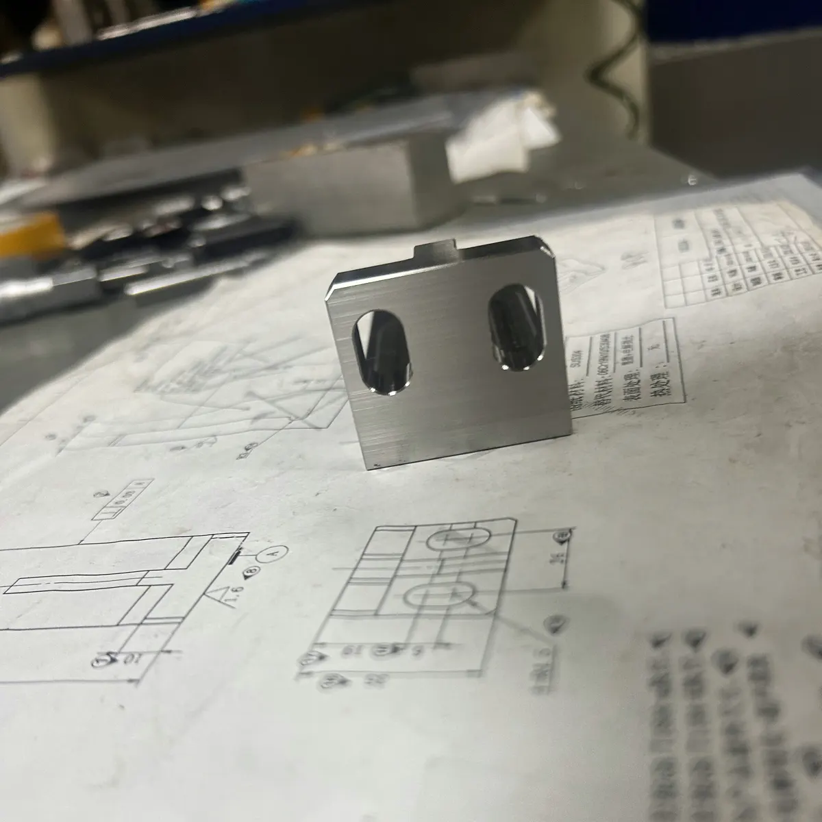
ISO 2768 and IT grades
ISO 286 defines standard tolerance grades from IT01 to IT18. A lower number means a tighter tolerance, and the same grade allows a larger tolerance on a larger size. Values below are the total tolerance band in µm for the grades most relevant to machining.
| Grade | 1–3 mm | 6–10 mm | 18–30 mm | 50–80 mm | 120–180 mm | 250–315 mm |
|---|---|---|---|---|---|---|
| IT5 | 4 | 6 | 9 | 13 | 18 | 23 |
| IT6 | 6 | 9 | 13 | 19 | 25 | 32 |
| IT7 | 10 | 15 | 21 | 30 | 40 | 52 |
| IT8 | 14 | 22 | 33 | 46 | 63 | 81 |
| IT9 | 25 | 36 | 52 | 74 | 100 | 130 |
| IT10 | 40 | 58 | 84 | 120 | 160 | 210 |
| IT11 | 60 | 90 | 130 | 190 | 250 | 320 |
| IT12 | 100 | 150 | 210 | 300 | 400 | 520 |
| IT13 | 140 | 220 | 330 | 460 | 630 | 810 |
| IT14 | 250 | 360 | 520 | 740 | 1000 | 1300 |
Example: IT7 for an 18–30 mm size is 21 µm, or 0.021 mm in total. Fits such as H7 use this grade.
General tolerances are wider than many engineers expect. Between about 6 and 120 mm, ISO 2768-f is roughly IT12, ISO 2768-m is roughly IT13–IT14 and ISO 2768-c is roughly IT15–IT16. These are rough comparisons, not conversions. The practical point: a fit like H7 is several grades tighter than anything ISO 2768 gives you, so it always needs its own callout.
Tolerance stack-ups in plate assemblies
Tolerances add up when plates and brackets are stacked. Take three plates, each 10 mm thick, left on ISO 2768-m. At 10 mm, class m allows ±0.2 mm per plate.
| Method | Calculation | Stack tolerance | Stack height range |
|---|---|---|---|
| Worst case | 0.2 + 0.2 + 0.2 | ±0.6 mm | 29.4 – 30.6 mm |
| Statistical (RSS) | √(0.2² + 0.2² + 0.2²) | ±0.35 mm | about 29.65 – 30.35 mm |
If the assembly needs 30 ±0.15 mm, neither method is close. The options are to tolerance the plate thicknesses individually, add a shim or adjustment, or redesign so fewer parts set the critical height. RSS gives a more realistic estimate for larger batches, but it gives no guarantee on any single assembly.
Features that need an individual tolerance
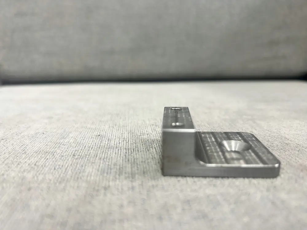
Ask one question for each dimension: what happens if it sits at the edge of the general tolerance? If the answer is “the part doesn’t fit or doesn’t work”, give it its own tolerance.
| Feature | Typical callout |
|---|---|
| Locating dowel pin holes | Fit such as H7, with position to datums |
| Bearing bores | Fit chosen for the bearing, such as H7 |
| Hole pattern bolted to a mating part | Position tolerance to datums |
| O-ring and seal grooves | Width and depth to the seal maker’s recommendation |
| Stacked thicknesses | Individual thickness tolerance |
| Tapped holes | Thread class and minimum full thread depth |
Common mistakes
- Tight tolerances on every dimension. Slows machining and inspection everywhere for no functional benefit. Tolerance what matters and leave the rest on ISO 2768.
- Relying on ISO 2768 for fits. At 50 mm, class m allows ±0.3 mm. A bearing seat or dowel hole needs a fit, not a general tolerance.
- Ignoring stack-ups. Five parts at ±0.1 mm can stack to ±0.5 mm worst case.
- Tight tolerances on thin walls. Thin walls deflect during cutting and after unclamping. Keep walls as thick as the design allows and accept wider tolerances on thin features.
- No general tolerance note at all. The shop has nothing to fall back on, and every untoleranced dimension becomes a question.
- Undefined “TYP” or reference dimensions. State in the notes what tolerance applies to them.
- Tolerances applied before finishing without saying so. Coatings such as anodizing change size. See our guide to anodizing aluminum plates and brackets.
Recommended drawing notes for plates and brackets
- Title block: “General tolerances: ISO 2768-1:1989 m”
- Locating holes: fit tolerance plus position to datums A/B/C
- Critical faces: individual flatness or perpendicularity
- Threads: thread class and minimum full thread depth
- Finished parts: state whether dimensions apply before or after surface treatment
ISO 2768 also states that a part exceeding a general tolerance should only be rejected if its function is impaired. That is one more reason to put the tolerances that matter on the features themselves.
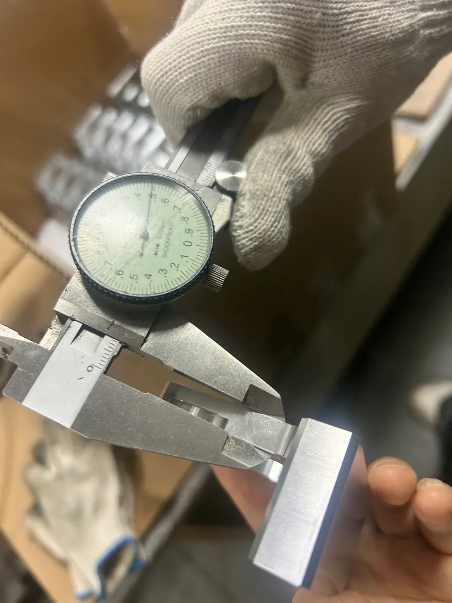
For more items to review before release, see our DFM checklist for mounting plates and brackets, and examples of machined mounting and adapter plates and machined brackets.
Not sure which dimensions on your plate or bracket need their own tolerance? Send us your drawing and we will point out the critical features that are only covered by the general tolerance.