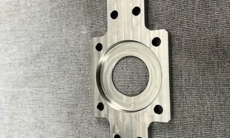
A mounting plate can pass every dimension at final inspection and still come back from anodizing with dowel pins that won’t go in and screws that won’t start. Anodizing is not a coat of paint sitting on top of the part. It converts the aluminum surface into oxide, and part of that oxide grows outward, so holes get smaller, threads get tighter and plates get thicker.
This guide covers which features on aluminum plates and brackets are affected, by roughly how much, and how to call it out on the drawing so the machine shop and the finisher work to the same numbers.
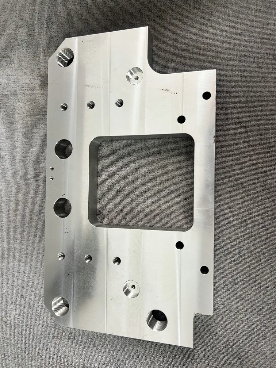
How much does anodizing change dimensions?
As a rule of thumb, about half of the coating thickness grows outward from the original surface and about half penetrates into the metal. The exact split varies with alloy and process, so confirm it with your finisher for critical parts.
- Type II (sulfuric acid) anodizing: typically about 5–25 µm thick. Used for corrosion protection, appearance and color, including black and clear finishes on brackets and covers.
- Type III (hardcoat) anodizing: typically about 25–50 µm thick. Used where wear resistance matters, for example on sliding or locating surfaces.
What this means on a feature:
- Each coated surface grows by about half the coating thickness.
- A hole or bore shrinks in diameter by about the full coating thickness, because both sides grow inward.
- A plate grows in thickness by about the full coating thickness, because both faces grow outward.
Critical areas on mounting plates and brackets
1. Precision dowel pin holes (H7 fits)
Locating holes on mounting plates often carry tight tolerances. A Ø6 H7 hole, for example, is +0.012 / 0 mm. A 50 µm Type III hardcoat can reduce that hole’s diameter by about 0.050 mm, roughly four times the whole tolerance band. The dowel pin will bind or not enter at all.
Solution: mask the hole before anodizing, or machine the bore oversize by the expected coating build-up so it finishes within tolerance after coating. If the hole is masked, it stays bare aluminum.
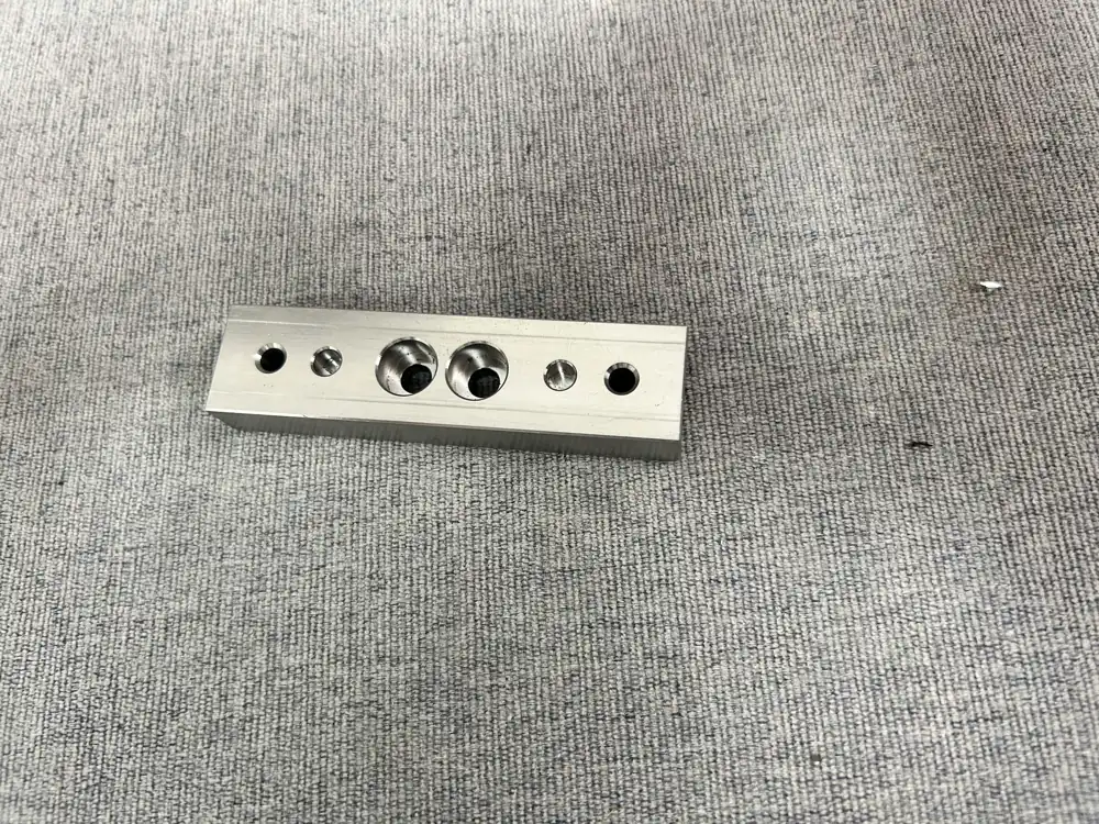
2. Tapped threads (M3–M8 internal threads)
Small internal threads on brackets are especially sensitive to coating build-up. Because of the 60° thread angle, the pitch diameter of a thread changes by about four times the build-up on each flank. A 25 µm build-up per surface can close the pitch diameter of an internal thread by about 0.1 mm, which can use up most or all of the thread’s tolerance on small sizes.
Solution: for small threads, especially below M4 or under Type III hardcoat, either cut them with oversize taps before anodizing or mask them with plugs. Another option is to tap the threads after anodizing, leaving bare aluminum in the thread.
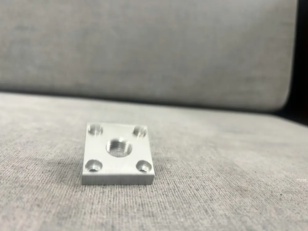
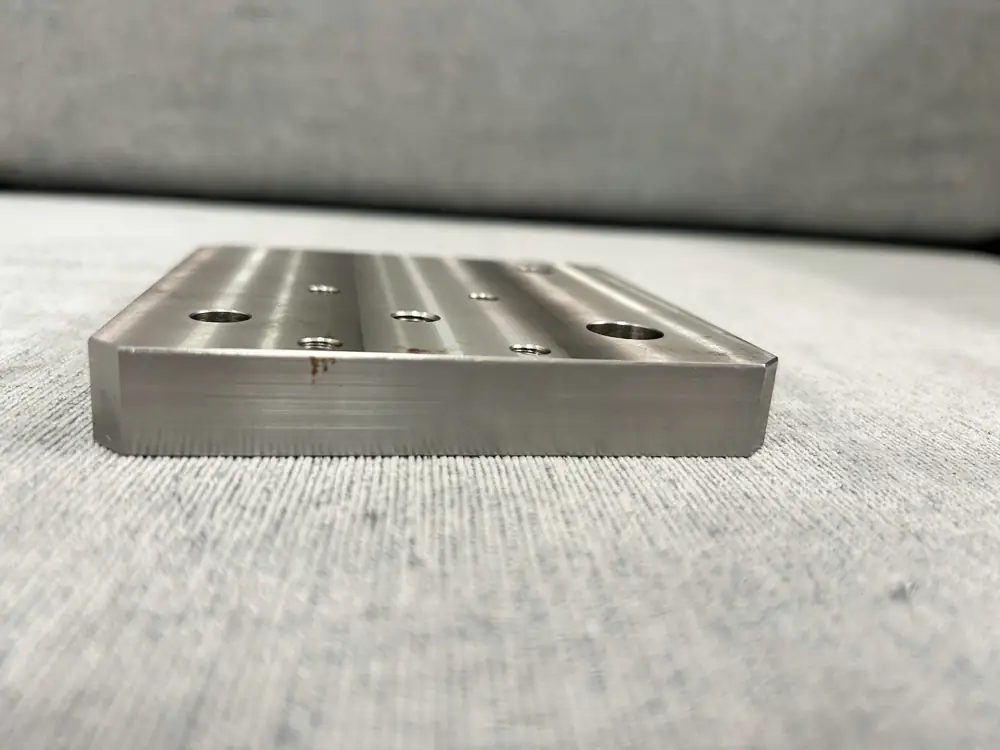
3. Plate thickness and stacked mating faces
When several anodized plates are stacked in an assembly, the build-up adds up at every contact face. Take four plates with Type III hardcoat at about 25 µm build-up per side: each plate grows about 0.05 mm in thickness, so the stack grows about 0.2 mm in total. On a stack that sets a height or a gap, that can be enough to push the assembly out of tolerance.
Solution: check tolerance stack-ups with the coated thickness, not the machined thickness. For flatness- or height-critical faces, specify whether the tolerance applies before or after anodizing, or mask those faces.
How to call out anodizing on technical drawings
Most disputes between a buyer, a machine shop and a finisher come from drawings that don’t say when dimensions apply. Three notes avoid most of them:
- State when dimensions apply. For example: “All dimensions and tolerances apply after anodizing.” This tells the machine shop to allow for build-up on toleranced features. If only a few features are critical, you can instead say which dimensions apply before finishing.
- Show masking clearly. For example: “Mask all H7 dowel holes and M4 threads prior to anodizing.” Mark the masked areas on the drawing, not only in a note.
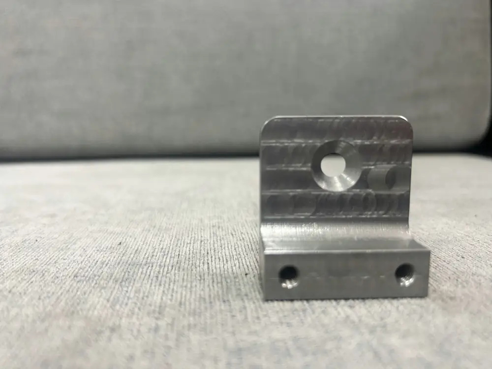
- Specify coating type and thickness range. For example: “Finish: Anodize per MIL-A-8625 Type III, Class 2 (black), coating thickness 50 ± 5 µm.”
Check the coating, not just the part
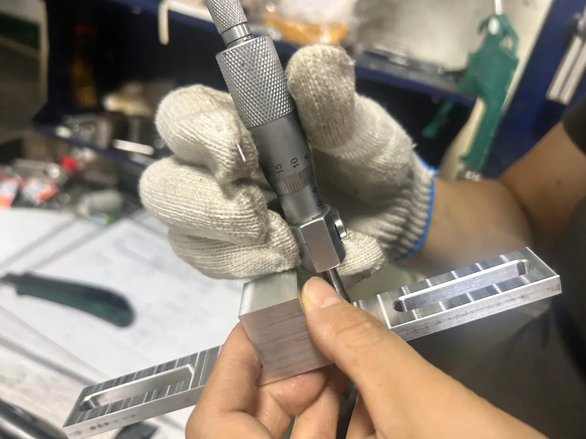
Coating thickness can vary from batch to batch. On parts with critical fits, ask for coating thickness to be measured on finished parts, and check pin holes and threads with gauges after anodizing, not only before.
For other features to review before release, see our DFM checklist for mounting plates and brackets. You can also see examples of machined mounting and adapter plates and machined brackets.
If your plate or bracket will be anodized, mark the critical holes, threads and faces on the drawing and send it to us for review. We will raise any feature where coating build-up affects the fit.