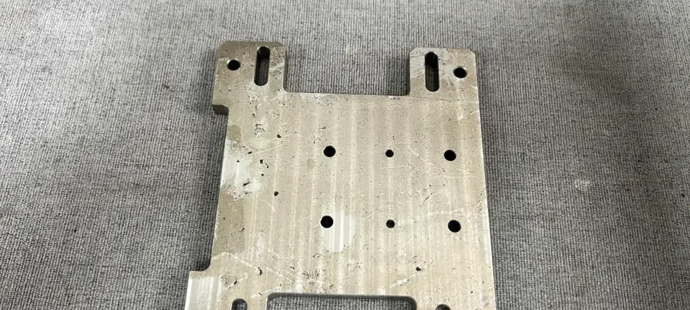
Most of the questions we raise during drawing review at VANTECH CNC come back to the same few details: a sharp inside corner, a tight tolerance on a face that doesn’t mate with anything, or a feature that forces one more setup. None of them are mistakes in the design intent. They are just details that are easier to settle before the drawing is released than after the quote.
This checklist covers what we look at on mounting plates, adapter plates and brackets. Use it before you send a drawing to any machine shop, ours included.
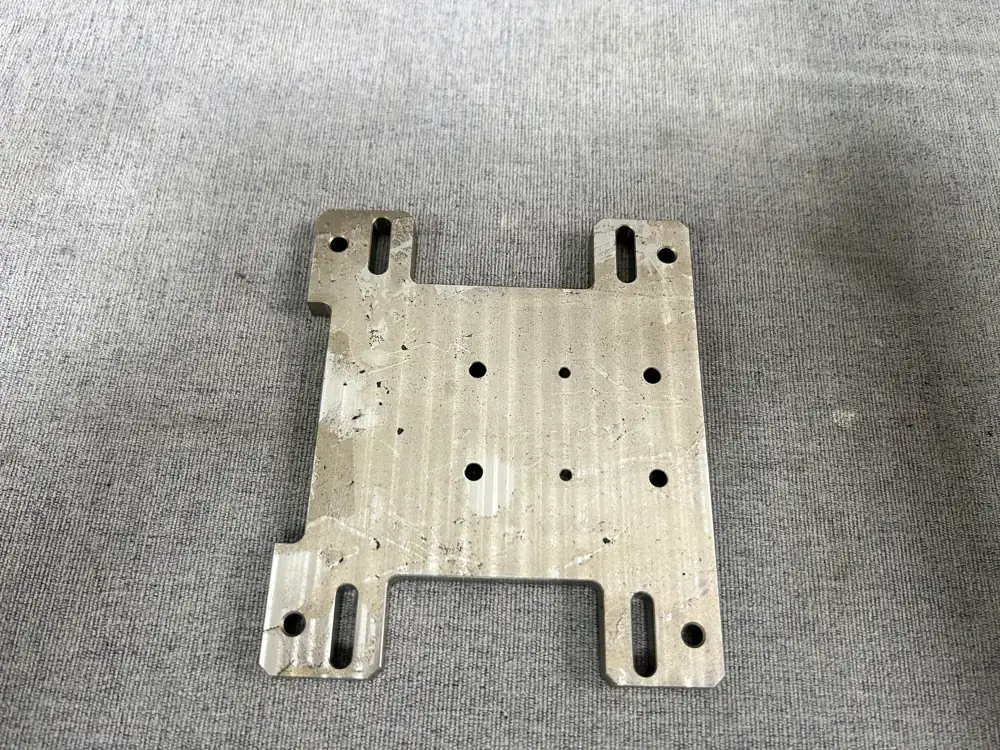
1. Geometry and wall thickness
- Minimum wall thickness. As a starting point, keep metal walls (aluminum, stainless steel) at 1.5–2.0 mm or more, and plastic walls at 2.0–3.0 mm or more. Thinner walls flex under cutting forces, which shows up as chatter marks or walls that measure out of shape once unclamped.
- Internal corner radii. End mills are round, so an internal 90° corner always ends up with a radius. Make the corner radius slightly larger than the cutter radius. For a 6 mm cutter (3 mm radius), a 3.5 mm corner radius lets the tool keep moving through the corner instead of stopping in it, which gives a better finish and longer tool life. If a mating part really needs a square corner, ask about corner relief (dog-bone) cuts.
- Pocket depth. Keep pockets within about 4× the cutter diameter, for example around 40 mm deep for a 10 mm cutter. Deeper pockets need long-reach tools that deflect, so walls taper and dimensions drift.
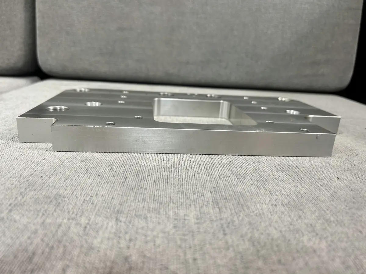
2. Holes and threads
- Blind hole bottoms. A standard drill leaves a 118° or 135° cone at the bottom of a blind hole. Specify a flat bottom only where something actually seats on it, such as a locating pin, because it needs an extra end mill operation.
- Tap drill depth. For a tapped blind hole, drill several thread pitches deeper than the full-thread depth you need (3–4 pitches is a common allowance), so the tap’s lead chamfer has room and the thread is complete where you need it.
- Threads in thin plates. On aluminum plates under about 5 mm that carry load or are assembled and taken apart often, consider thread inserts (Helicoil or Keensert type) and check there is enough material around each hole for them.
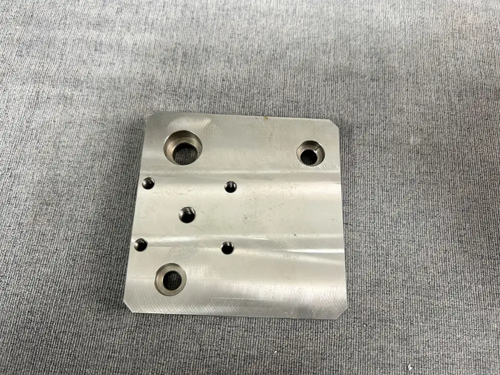
3. Tolerances and datums
- Tight tolerances only where they work. Use a general tolerance such as ISO 2768-m for outside profiles and non-critical features. Keep tight tolerances for dowel holes (for example an H7 fit), bearing seats and faces that locate against another part. Every tight tolerance adds machining and inspection time.
- One datum scheme. Dimension hole patterns on plates and brackets from one datum edge, face or hole. When features reference different starting points, small errors add up across the pattern.
On an adapter plate this matters twice: both hole patterns should come from the same datum, so the two interfaces line up. Our mounting and adapter plates page shows the drilled, windowed and slotted plates we machine.
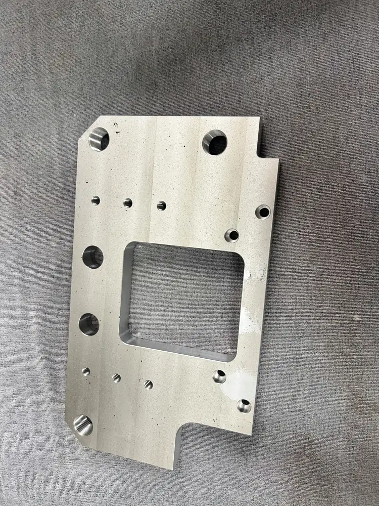
4. Clamping and setups
- A flat clamping surface. The part needs at least one flat, parallel pair of surfaces we can hold in a vise or on a fixture plate. Brackets with only angled or curved outside faces may need a custom fixture or extra stock that is cut off later.
- Fewer setup directions. Where you can, put counterbores, pockets and locating holes on one or two faces. Each extra orientation means re-clamping and re-indicating the part, which adds time and a chance for misalignment between features.
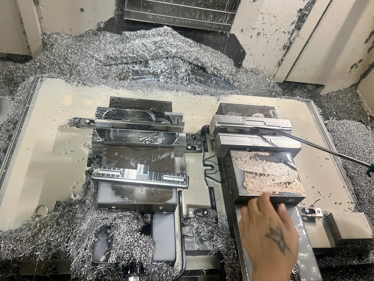
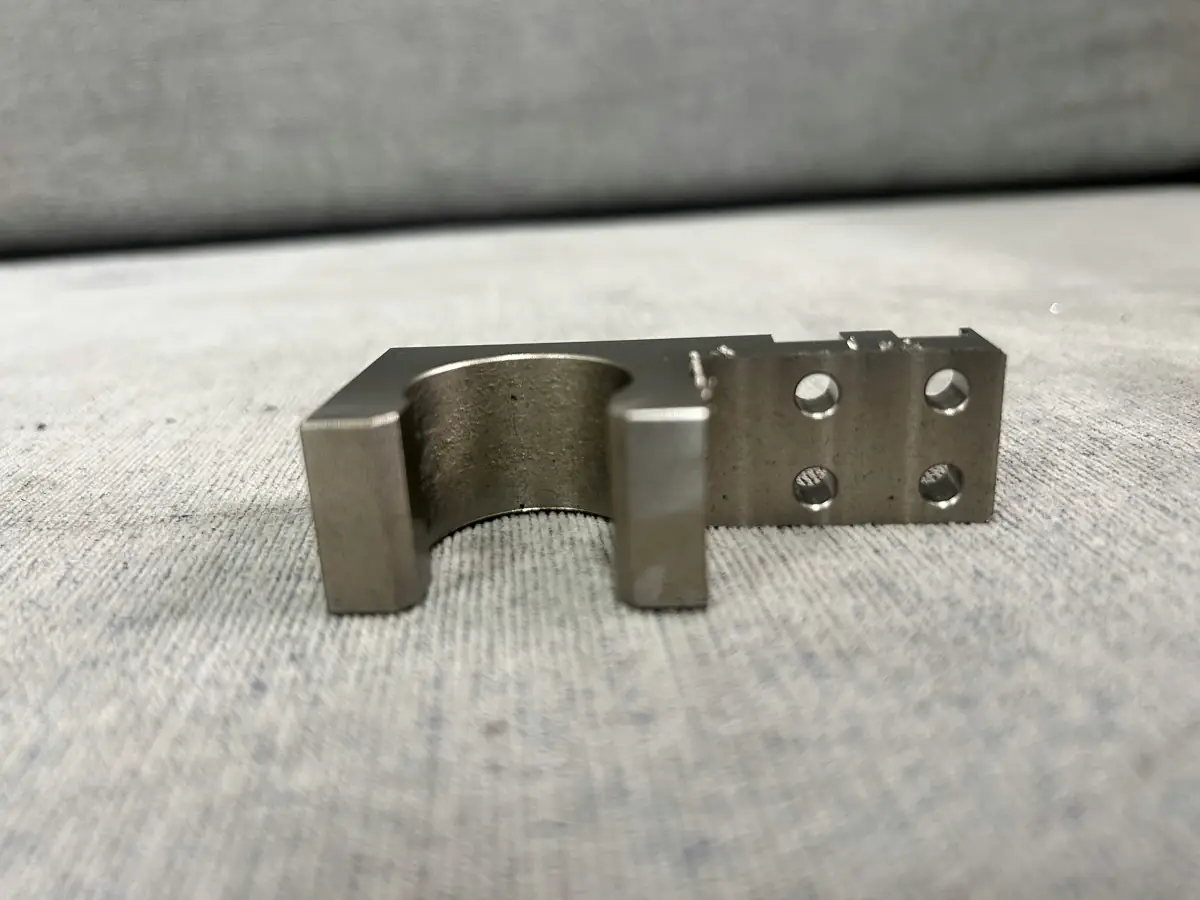
Slotted and stepped brackets are a good example. Compare the features on our slotted fixture bracket and slotted adjustment bar, or see more machined bracket examples.
5. Material and finishing
- Large aluminum plates. For large 6061 or 7075 plates, specify stress-relieved stock such as 6061-T651. On flatness-critical parts, plan for rough machining, releasing the part, then finish machining, so stress released during roughing doesn’t end up as warp in the finished plate.
- Anodizing and plating allowance. Coatings add material. Hard anodizing is typically about 25–50 µm thick, with roughly half of it building up on the surface. State on the drawing whether critical sizes, such as H7 pin bores or threads, apply before or after finishing, and mask them if needed.
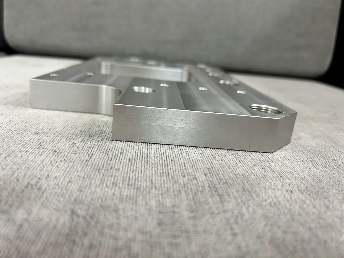
For smaller drilled blocks, see our compact drilled mounting block and drilled machined block.
What to send with your drawing
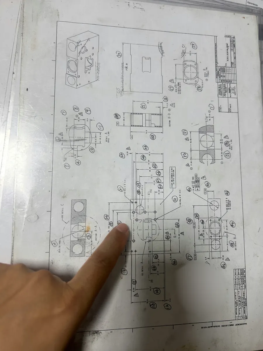
- 2D drawing (PDF) and 3D model (STEP), with datums and critical features marked
- Material grade and quantity per part number
- Surface finish, and which faces or holes it applies to
- The mating part, if the plate or bracket adapts two interfaces
- Delivery destination and target date
We will point out any of the items above that affect cost or lead time. See what we machine on our capabilities page, or send us your drawing.